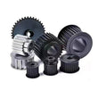
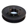
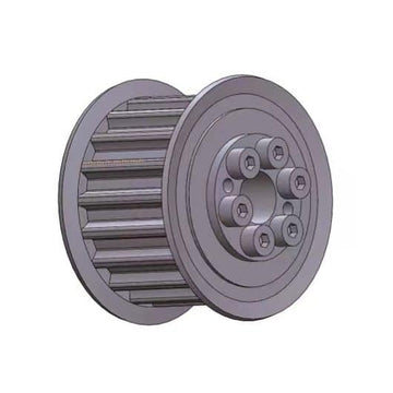
Timing Pulley
Timing Pulley
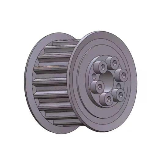
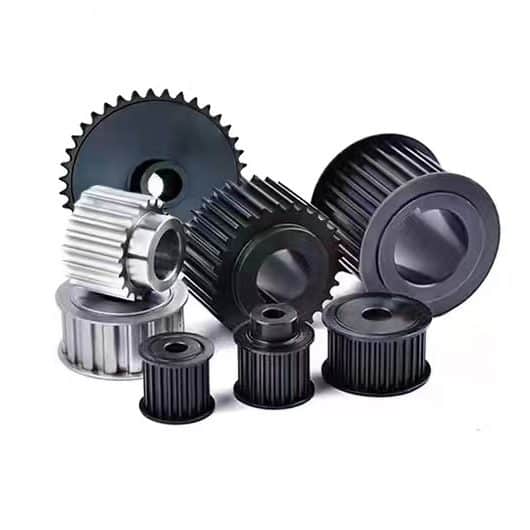
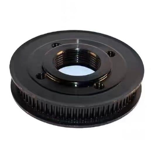
Timing pulleys are generally made of carbon steel, and can also be processed with aluminum alloy, copper, nylon and other materials according to customer requirements; if the outer diameter of the timing pulley is greater than 250mm, cast iron is generally used. The characteristics of arc gear transmission: arc gear transmission pilot meshing transmission, the value is suitable for helical gears, not for spur gears. The relative radius of curvature is larger than that of the involute, and the contact strength is higher than that of the involute. The sensitivity to center distance changes is greater than that of involutes. During processing, the requirements for cutting depth are high, radial displacement cutting is not allowed, and assembly errors are strictly controlled.
Outline dimension of circular arc tooth synchronous belt
| Groove | Pitch pb | alveolar depth hg | Cogging arc radius R | Addendum circle half angle r1 | Alveolar width s | Double pitch distance 2δ | Tooth angle |
| 3M | 3 | 1.28 | 0.91 | 0.26~0.35 | 1.90 | 0.762 | ≈14° |
| 5M | 5 | 2.16 | 1.56 | 0.48~0.52 | 3.25 | 1.144 | ≈14° |
| 8M | 8 | 3.54 | 2.57 | 0.78~0.84 | 5.35 | 1.372 | ≈14° |
| 14M | 14 | 6.20 | 4.65 | 1.36~1.50 | 9.80 | 2.794 | ≈14° |
| 20M | 20 | 8.60 | 6.84 | 1.95~2.25 | 14.80 | 4.320 | ≈14° |
Outline dimension of trapezoidal tooth synchronous belt
| model | MXL | XXL | XL | L | h | XH | XXH | |||||||
| alveolar bottom width bw | 0.84±0.05 | 1.14±0.05 | 1.32±0.05 | 3.05±0.10 | 4.19±0.13 | 7.90±0.15 | 12.17±0.18 | |||||||
| alveolar depth hg | 0.69 | 0 | 0.84 | 0 | 1.65 | 0 | 2.67 | 0 | 3.05 | 0 | 7.14 | 0 | 10.31 | 0 |
| -0.05 | -0.05 | -0.08 | -0.10 | -0.13 | -0.13 | -0.13 | ||||||||
| Addendum fillet radius rt | 0.13 | 0.05 | 0.30 | 0.05 | 0.64 | 0.05 | 1.17 | 0.13 | 1.60 | 0.13 | 2.39 | 0.13 | 3.18 | 0.13 |
| 0 | 0 | 0 | 0 | 0 | 0 | 0 | ||||||||
| Twice pitch pitch 2β | 0.508 | 0.508 | 0.508 | 0.762 | 1.372 | 2.794 | 3.048 | |||||||
| Alveolar half angle Φ+1.5° | 20 | 25 | 25 | 20 | 20 | 20 | 20 | |||||||
| root fillet radius rb | 0.35 | 0.35 | 0.41 | 1.19 | 1.60 | 1.98 | 3.96 | |||||||

Synchronous pulley specification model identification
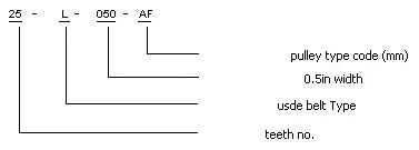
Representation
1. Model of synchronous pulley
2. Tooth shape size, tolerance and technical parameters
3. Dimension table of tooth surface width of various synchronous pulleys
The part number of the synchronous pulley is defined and identified by three parameters: pitch, number of teeth and applicable synchronous belt width. For example: part number AF29-8M-30 meaning: 8mm pitch, 29 teeth, AF means synchronous pulley code, and 30mm synchronous belt width is applicable.
The pitch of the synchronous pulley refers to the distance between the centers of adjacent teeth, in millimeters. The pitches corresponding to the letters are as follows: 2M = Mini Extra Light = 2mm pitch; 3M = Extra Light = 3mm pitch; 5M = Light = 5mm pitch; 8M = Heavy = 8mm pitch.
Synchronous pulley width - refers to the maximum synchronous belt width that can run on the synchronous pulley, the width value is one hundredth of the corresponding value on the part number, and the unit is mm.

